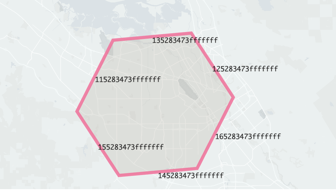
Directed edge mode

An H3 Directed Edge index (mode 2) represents a single directed edge between two cells (an "origin" cell and a neighboring "destination" cell). The components of the H3 Directed Edge index are packed into a 64-bit integer in order, highest bit first, as follows:
- 1 bit reserved and set to 0,
- 4 bits to indicate the H3 Unidirectional Edge index mode,
- 3 bits to indicate the edge (1-6) of the origin cell,
- Subsequent bits matching the index bits of the origin cell.
Bit layout of H3Index for directed edges
The layout of an H3Index is shown below in table form. The interpretation of the "Mode-Dependent" field differs depending on the mode of the index.
| 0x0F | 0x0E | 0x0D | 0x0C | 0x0B | 0x0A | 0x09 | 0x08 | 0x07 | 0x06 | 0x05 | 0x04 | 0x03 | 0x02 | 0x01 | 0x00 | |
|---|---|---|---|---|---|---|---|---|---|---|---|---|---|---|---|---|
| 0x30 | Reserved (0) | Mode (2) | Edge | Resolution | Base cell | |||||||||||
| 0x20 | Base cell | Digit 1 | Digit 2 | Digit 3 | Digit 4 | Digit 5 | ||||||||||
| 0x10 | Digit 5 | Digit 6 | Digit 7 | Digit 8 | Digit 9 | Digit 10 | ||||||||||
| 0x00 | Digit 10 | Digit 11 | Digit 12 | Digit 13 | Digit 14 | Digit 15 | ||||||||||